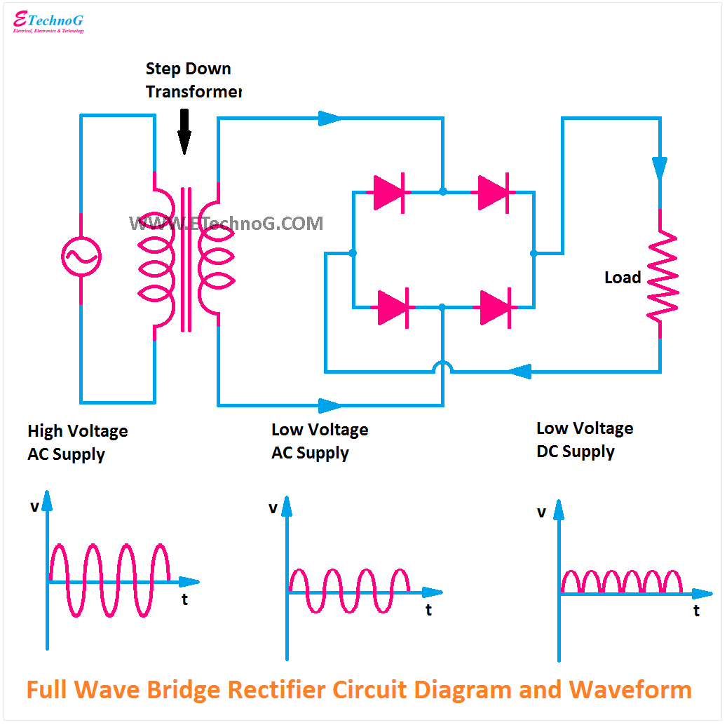
Why is this ideal diode bridge rectifier simulation in ltspice not Bridge rectifier circuit diagram and waveform Rectifier bridge full wave capacitor filter half formula calculation electric positive cycle flow voltage shocks filters waves current operation during full bridge rectifier schematic
full bridge rectifier circuit diagram - Wiring Diagram and Schematics
Rectifier wave bridge full circuit operation contents its Full bridge rectifier circuit Full wave bridge rectifier – circuit diagram and working principle
Full wave bridge rectifier
Full-wave bridge rectifierFull wave bridge rectifier schematic Full bridge rectifier circuit diagramRectifier bridge wave full.
Bridge rectifier wiring diagramScope noob: bridge rectifier Bridge rectifier diagram discount compare, save 44%Full wave bridge rectifier.

Bridge rectifier circuit diagram ppt
Full wave bridge rectifierRectifier half Full bridge rectifier circuit diagramFull wave bridge rectifier schematic.
Bridge rectifier circuit, construction, working, and typesFull wave rectifier-bridge rectifier-circuit diagram with design & theory [diagram] h bridge circuit diagramRectifier bridge circuit working diagram power load type its operation used types controlled.

Rectifier bridge schematic symbols full wave noob scope shunt hackaday rectification rotating before
Full wave bridge rectifier with capacitor filter design calculation andBridge rectifier : circuit diagram, types, working & its applications Full bridge rectifier circuit diagramRectifier wave bridge full circuit diagram diode voltage operation fig its shown below inverse peak disadvantages advantages value when.
The full-wave bridge rectifier .


![[DIAGRAM] H Bridge Circuit Diagram - MYDIAGRAM.ONLINE](https://i2.wp.com/theorycircuit.com/wp-content/uploads/2018/03/full-wave-bridge-rectifier-circuit-diagram.png)


